
There are two types of glass heat exchangers, coil type and shell and tube type heat exchangers.
Coil type heat exchangers are of all-glass design. There are no internal sealing problems as the coil battery is welded into the jacket making a one piece unit. Coil type heat exchanger are used for condensation of vapours and cooling of liquid.
The heat transfer coefficients also varies from one size of condenser to another but as a guide, the table below gives as indication of the performance of condenser at atmospheric pressure, using water (inlet temperature 30° C ) as a coolant in the coils and steam condensing in the jackets. The figures do not show the maximum performance of the units but are a general indication of typical working conditions.
| Jacket sideMedium | Vapour to be condensed | Liquid | Gas |
|---|---|---|---|
| Coil side medium | Cooling Water | Cooling Water | Cooling Water |
| Heat transf. coeff. | - | - | - |
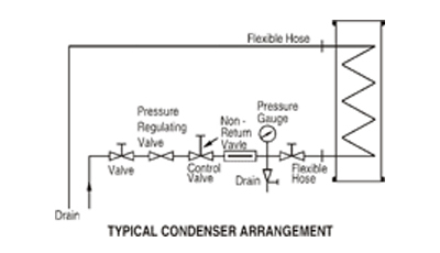
When connecting coil-type condensers to the coolant supply, adequate flexible hose should be used to ensure that stresses are not transmitted to the glass.
Condenser should never be operated with steam in the coils. They should always be used with an adequate flow of coolant through the coils and care should be taken to ensure that the coolant does not become heated to boiling point.
Coolant control valves should always be turned ON and OFF slowly, particularly when air is present in the line. Coolant should be allowed to drain freely to a point as closed as practicable to the heat exchangers.
Care should be taken in arranging the coolant supply in order to that water hammer is avoided. A uniform, continuous supply of coolant should be ensured.
If a condenser is out of service for any length of time, it is advisable to drain the coils, especially in winter when suitable precautions should be taken to prevent freezing of any water remaining after draining.
Brine or other coolants in closed circuit can be used as a coolant provided the suitable precautions against water hammer are taken.
Condensers can be mounted in series to provide lager surface area. Generally condensers should be mounted vertically only.
The maximum pressure in the coil is 2.7 Bar g the maximum differential pressure
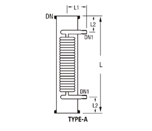
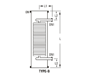
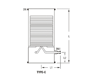
| COOLANT JACKETTHROUGH FCSA* | ||||||||||
|---|---|---|---|---|---|---|---|---|---|---|
| AREAz (m²) | DN | DN1 | L | L1 | L2 | TYPE | CAP. LTR. | PUT Kg/h | SHELL (cm²) | CAT. REF. |
| 0.2 | 40 | 16 | 610 | 85 | 100 | A | 1.0 | 700 | 4.5 | SHE 1.5/2 |
| 0.3 | 50 | 16 | 610 | 90 | 100 | A | 1.25 | 1200 | 5 | SHE 2/3 |
| 0.3 | 80 | 80 | 610 | 90 | 100 | A | 2 | 1200 | 5 | SHE 3/3 |
| 0.5 | 100 | 20 | 610 | 120 | 100 | A | 4 | 2200 | 18 | SHE 4/5 |
| 0.6 | 100 | 20 | 760 | 120 | 100 | A | 6 | 2200 | 30 | SHE 4/6 |
| 1.0 | 150 | 25 | 610 | 150 | 100 | B | 9 | 2300 | 52 | SHE 6/10 |
| 1.5 | 150 | 25 | 840 | 150 | 125 | B | 11 | 2300 | 52 | SHE 6/15 |
| 2.5 | 225 | 25 | 790 | 180 | 125 | B | 18 | 3000 | 142 | SHE 9/25 |
| 2.5 | 300 | 25 | 610 | 250 | 125 | B | 25 | 2750 | 210 | SHE 12/25 |
| 4.0 | 300 | 25 | 900 | 250 | 125 | B | 35 | 4200 | 258 | SHE 12/40 |
| 4.0 | 400 | 25 | 600 | 350 | 125 | B | 55 | 4800 | 450 | SHE 16/40 |
| 5.0 | 400 | 25 | 700 | 350 | 125 | B | 65 | 5800 | 450 | SHE 16/50 |
| 6.0 | 450 | 25 | 760 | 325 | 150 | B & C | 100 | 5800 | 820 | SHE18/60 |
| 8.0 | 450 | 25 | 900 | 325 | 150 | B & C | 110 | 6100 | 820 | SHE 18/80 |
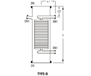
Type SHEB 4, SHEB 6 and SHEB 9 glass coil-type boiler are normally mounted in external circulatory loops using a spherical vessel as the main still. They should not be installed in the bottom of a flask or column.
The other types of glass coil-type boilers detailed on this page are again mounted in circulatory loops but as their nominal bore is same at the top and bottom, these units can, under certain circumstances, be installed one above the other to achieve multiples of the basic heat transfer area.
The maximum pressure in the coils is 3.0 barg. The maximum differential pressure across the coils is 3.0 bars. Please refer to the performance data for glass coil-type.
| DN 150 | DN 225 | DN 300 | |||||
|---|---|---|---|---|---|---|---|
| Details of Construction | Max | Min | Max | Min | Max | Min | |
| ShellSide | GlassShell | 2.0 bar.g | Vacuum | 1.0bar.g | Vacuum | 0.7bar.g | Vacuum |
| Steel Shell | 3.5bar.g | Vacuum | 3.5bar.g | Vacuum | 3.5bar.g | Vacuum | |
| Tube Side | Glass Bonnet Single Pass | 2.0 bar.g | Vacuum | 1.0bar.g | Vacuum | 0.7bar.g | Vacuum |
| Metal Bonnet Triple Pass | 2.5bar.g | Vacuum | 2.5bar.g | Vacuum | 2.5bar.g | Vacuum | |
The maximum permissible steam pressure at the coil inlets of boilers is 3.0 barg which is equivalent to temperature of about 143°C with saturated steam. Higher temperature can be achieved by using heat.
The heat transferred in most sizes can be considered on average as 250 Kcal/hr – m² °c a steam pressure in the coils of 3.0 Bar g, although this figure declines marginally at lower pressure.
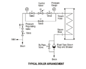
Flexible hoses must be used on the coil inlet and outlet and must have sufficient fall to avoid the collection of condensate.
To avoid the possibility of steam hammer, the steam main should be adequately trapped.
To clear the line of the very heavy condensate flow produced on start-up by-pass valves must be installed around the trap on the coil outlet.
Control valves and pressure gauges should be positioned near to the heat exchanger.
Coil type boilers should not be fitted at the bottom of flasks or columns. They are designed to be mounted on an external circulatory loop, this ensures a rapid uni - directional flows across the heating surfaces, which improves the heat transfer performance and promotes smooth operation.
The steam pressure should always be adequate enough to ensure effective and smooth condensate removal. This pressure will vary according to conditions of use and size of heat exchanger. For example, with the SHEB 12/12 and SHEB 450, a minimum pressure of 2 bar.g will probably be required.
On start-up, the steam should be admitted positively and progressively to the coil battery to remove the condensate as it is formed and with the by-pass valve left open until a uniform flow of condensate is being vented.
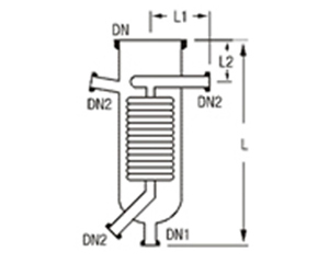
| FCSA | ||||||||||
|---|---|---|---|---|---|---|---|---|---|---|
| Area (m) | DN | DN1 | DN2 | l | l1 | l2 | Cap. (cm²) | jacket Ltr. | Type | Cat. Ref. |
| 0.15 | 100 | 25 | 25 | 380 | 125 | 100 | 40 | 2 | A | SHEB 4 |
| 0.15 | 100 | 25 | - | 405 | 125 | 100 | 41 | 3 | B | SHEB 4/4 |
| 0.50 | 150 | 40 | 25 | 455 | 150 | 90 | 51 | 5 | A | SHEB 6 |
| 0.50 | 150 | 25 | - | 510 | 150 | 100 | 51 | 7 | B | SHEB 6/6 |
| 1.50 | 225 | 40 | 25 | 710 | 180 | 140 | 147 | 16 | A | SHEB 9 |
| 1.20 | 225 | 25 | - | 710 | 180 | 115 | 193 | 20 | B | SHEB 9/9 |
| 2.00 | 300 | 25 | 25 | 700 | 215 | 135 | 330 | 40 | B | SHEB 12/12 |
* FCSA - Free Cross Section Area
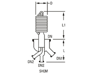
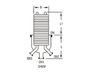
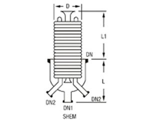
Immersion heat exchangers are used to control exothermic reactions in glass vessels.
In most applications, cooling water is used in the coils, but they can also be used with steam.
In the latter case the coils must always be completely immersed in the liquid. The maximum pressure in the coils is 3.0 bar g. the maximum differential pressure across.
| AREAz (m²) | DN | DN1 | dn2 | l | L1 | d | Cat. Ref. |
|---|---|---|---|---|---|---|---|
| 0.50 | 150 | 40 | 25 | 230 | 330 | 145 | SHEM 6 |
| 0.70 | 225 | 25 | 25 | 275 | 205 | 210 | SHEM 9 |
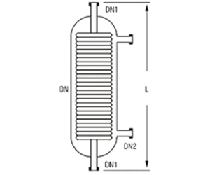
Product coolers are general-purpose coolers used for cooling of products from distillation columns. Coolers are connected directly to the product outlet of the column by means of DN1. The product then flows from the top to the bottom of the unit through the coil battery across which the cooling water flows counter currently from bottom to top.
Angled hose connections are recommend for connections of cooling water Inlets and Outlets.
| Area (m²) | DN | DN1 | DN2 | l | Type | Cat. Ref. |
|---|---|---|---|---|---|---|
| 0.1 | 40 | 25 | 16 | 610 | A | SHEF 1/1 |
| 0.2 | 50 | 25 | 16 | 610 | A | SHEF 1/2 |
| 0.3 | 80 | 25 | 16 | 610 | A | SHEF 1/3 |
| 0.35 | 100 | 25 | 19 | 610 | A | SHEF 1/3.5 |
| 0.50 | 150 | 25 | 25 | 610 | B | SHEF 1/5 |
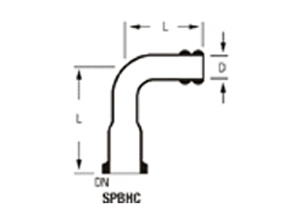
These glass connectors are used to connect flexible hoses to inlet and outlet of coil type condensers.
Shell and tube heat exchangers are available in various option depends upon required application, which are mentioned as under. Shell and tube heat exchangers are particularly suitable for application where large heat transfer area is required in relatively confined space.
Shell & tube heat exchangers are available in single-pass as well as multi - pass on tube side. Material of Construction of tube is Borosilicate Glass (3.3)
| Cat.Ref. | Shells | End Fittings | Tubes | Number of passes |
|---|---|---|---|---|
| SRGG | Glass | Glass | Glass | 1 |
| SRGM | Glass | Steel | Glass | 1/2/3 |
| SRMG | Steel | Glass | Glass | 1 |
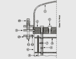
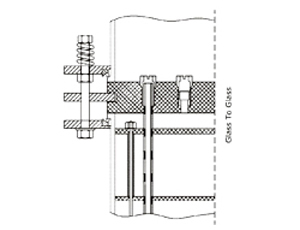
The glass tube are sealed individually into PTFE tube sheet with special PTFE sockets and pakcing. This unique ferrule type selling arrangement permits easy replacements and cleaning of tubes. Baffles on shell side ensure improved heat transfer by increased turbulence. Further details of construction can be seen in the diagram.
Sealing principle similar on all models
1. METAL / GLASS BONNET
2. PTFE TUBE SHEET
3. THREADED BUSH
4. GLASS TUBE
5. BAFFLE
6. METAL / GLASS SHELL
7. PTFE TUBE
8. TIE ROD IN PTFE
9. CAST IRON FLANGE
10. SPRING
11. SCREWED ROD OR NUT
12. INSERT
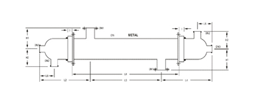
| Cat Ref. RGG/RMG | 6/3 | 6/4 | 6/5 | 6/6 | 9/6 | 9/8 | 9/10 | 9/12 | 12/12 | 12/16 | 12/21 | 12/26 | |||
|---|---|---|---|---|---|---|---|---|---|---|---|---|---|---|---|
| Area (m²) | 3 | 4 | - | 5 | 6 | 6 | 8 | - | 10 | 12.5 | 12 | 16 | - | 21 | 26 |
| DN | - | - | 150 | - | - | - | - | 225 | - | - | - | - | 300 | - | - |
| DN 1 | - | - | 80 | - | - | - | - | 100 | - | - | - | - | 150 | - | - |
| DN 2 | - | - | 50 | - | - | - | - | 50 | - | - | - | - | 80 | - | - |
| DN 3 | - | - | 25 | - | - | - | - | 40 | - | - | - | - | 40 | - | - |
| DN 4 | - | - | 50 | - | - | - | - | 50 | - | - | - | - | 50 | - | - |
| H 1 | - | - | 175 | - | - | - | - | 250 | - | - | - | - | 300 | - | - |
| H 2 | - | - | 150 | - | - | - | - | 205 | - | - | - | - | 240 | - | - |
| L 1 | 2534 | 3034 | - | 3834 | 4534 | 2864 | 3364 | - | 4164 | 4864 | 2916 | 3416 | - | 4216 | 4916 |
| L 2 | 440 | 440 | - | 440 | 440 | 690 | 690 | - | 690 | 690 | 730 | 730 | - | 730 | 730 |
| L 3 | 1650 | 2150 | - | 2950 | 3650 | 1480 | 1980 | - | 2780 | 3480 | 1450 | 1950 | - | 2750 | 3450 |
| L 4 | 440 | 440 | - | 440 | 440 | 690 | 690 | - | 690 | 690 | 730 | 730 | - | 730 | 730 |
| L 5 | 2030 | 2530 | - | 3330 | 4030 | 2030 | 2530 | - | 3330 | 4030 | 2030 | 2530 | - | 3330 | 4030 |
| L 6 | 155 | 155 | - | 155 | 155 | 175 | 175 | - | 175 | 175 | 200 | 200 | - | 200 | 200 |
| L 7 | 1350 | 1850 | - | 2650 | 3350 | 1030 | 1530 | - | 2330 | 3030 | 1000 | 1500 | - | 2300 | 3000 |
| L 8 | 1960 | 2460 | - | 3260 | 3960 | 1940 | 2440 | - | 3240 | 3940 | 1910 | 2410 | - | 3210 | 3910 |
| No. of Tubes | 11 | 14 | - | 19 | 24 | 7 | 9 | - | 13 | 17 | 17 | 5 | 7 | 73 151 | 13 |
| No. of Baffles | - | - | - | - | - | - | - | - | - | - | - | - | - | - | - |
| All glass tubes have an external diameter of 13mm or 14mm and a wall thickness of 1 mm | |||||||||||||||
The maximum permissible operating conditions in borosilicate glass 3.3 heat exchangers are detailed in the table below. Permissible operating pressure range (Bar g)
| Models | Side | DN 150 | DN 225 | DN 300 |
|---|---|---|---|---|
| SRGG | Shell | 0.2 | 1.0 | 0.75 |
| - | Tube | 0.2 | 2.0 | 1.0 0.75 |
| SRGM | Shell | 2.0 | 1.0 | 0.75 |
| - | Tube | 3.0 | 3.5 | 3.5 |
| SRMG | Shell | 3.5 | 3.5 | 3.5 |
Maximum operating temperature
shell and tube sides : - 40° C to 150° C.
Maximum temperature difference between the
shell side and tube side process fluids : 120° C.
Table given below indicates performance of glass shell and tube heat exchanger in several typical application. More specific advice can be given on receipt of details.
| Type of Heat transfer | Basis | Kcal/m² hr °C |
|---|---|---|
| Liquid - Liquid Cooling | Water-water | 500-600 |
| - | Water- organic solvents | 250-600 |
| - | Water-oil | 75-350 |
| - | Water - air | 25-250 |
| Liquid - -Gas Condensation | Water-water | 600-900 |
| - | Water- organic solvents | 400-600 |
| Evaporation | Steam - organic solvents | 400-600 |
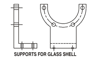
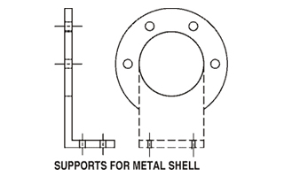
Generally two types of supports are used in shell and tube heat exchangers depends upon MOC of shell & tube heat exchangers.
MOC of these supports is MS.